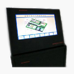
1、 A variety of on-site detection of a real-time data and standard alarm can be displayed directly on the main interface, and can use the touch screen to modify the corresponding set parameters;
2、you can use the map display function, the direct display of its location and operation;
3、alarm recording automatic storage, display the list of the alarm, can call the query, print and other functions;
Alarm processing: the scene of any gas concentration or other detection data to achieve or exceed the set value
4、The concentration value and the state are displayed on the gas alarm display screen which is located in the control room, and the corresponding signal to the monitoring system is provided.
5、The interface of the central control room system should give the corresponding detector position number and give the corresponding sound and light alarm signal. And record the alarm situation in the system, while the system alarm gives sound and light alarm. There should be an alarm area in the system plan (including the number and the specific installation location of gas transmitter), give the specific alarm.
6、Confirm alarm elimination: in the state of alarm, can be carried out by silencing the mute button, in the field of concentration is lower than the value of the alarm state can be confirmed by the alarm button to eliminate.
Can be extended to more than one external device driver, drive function (single phase equipment maximum 60A. three-phase equipment maximum 120A).
7、Can be extended to more than one external device driver, drive function strong (single phase equipment maximum 60A. three-phase equipment maximum 120A).
The alarm record and print:
To provide the scene a table curve display screen, and at the same time the scene of the alarm once the table working state recorded in the corresponding document, user-friendly query. System can automatically start the printer recording system alarm number, alarm time and alarm time and other parameters.
When alarm or alarm disappears, the system records the transducer working state of alarm to the corresponding file, convenient user query. And alarm system can be started automatically printer record system of area, such as alarm and alarm eliminate time parameters.
System self diagnosis function: with self-diagnosis function, the system run time when detecting device failure occurs, the transmitter on the liquid crystal display can be corresponding shows fault code, help you quickly find out the cause of the problem.
Four levels of password protection: system by the operator and manager, supervisor and engineer level 4 password protection, to prevent any loss of data, ensure the normal operation of the system.
Networked sharing: set up different geographical regions of the N main battle or sub control station, resource sharing through networks.
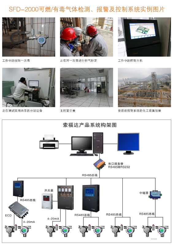
Main equipment of safety monitoring and control system of SFD-2000 major hazard source using RS485 communication

Serial number
|
name
|
unit |
quantity |
will match/selection |
| 1 |
Control computer |
table |
1 |
will match |
| 2 |
system work |
table |
1 |
will match |
| 3 |
21 "color LCD display |
table |
1 |
will match |
| 4 |
Mouse
|
a
|
1 |
will match |
| 5 |
Keyboard |
a |
1 |
will match |
| 6 |
21.5 "touch screen |
table |
1 |
will match |
| 7 |
Acousto-optic alarm |
table |
1 |
will match |
| 8 |
video expander |
a |
1 |
matching |
| 9 |
extended keyboard |
a |
1 |
matching |
| 10 |
Extension circuit board |
a |
2 |
will match |
| 11 |
communication expander |
table |
1-15 |
matching |
| 12 |
Siemens PLC |
table |
1 |
matching |
| 13 |
Siemens PLC communication, such as I/O expander |
a |
1-10 |
matching |
![]() Detection data and status display: in the alarm state, the system with the most intuitive graphic display of the detection data, color changes in the way, display the corresponding alarm point state. Specific as follows:
Detection data and status display: in the alarm state, the system with the most intuitive graphic display of the detection data, color changes in the way, display the corresponding alarm point state. Specific as follows:


 data download
 Links:
